Just recently I’ve started looking into ways to optimize the depth buffer precision for large draw distances and one specific approach caught my eye again. A technique which is now commonly referred to as Reverse Z. While it comes with just a few minor changes, the results can be quite considerable.
That considerable everyone should just go ahead and use it. 
Introduction
The general idea itself is actually very simple: instead of mapping the interval between the near and far plane
Why this actually increases the depth buffer precision is not directly obvious, but I will also not go into detail here. I’ve added some references to articles on this topic at the end of this post.
Simply put: this approach works very well in combination with floating point depth formats (16- or ideally 32-bit) and it utilizes the high precision in the numerical area around zero for distant objects. Using it in conjunction with normalized integer formats will not yield the expected precision improvements.
Sadly the overall knowledge about this approach is still a bit scattered through the Net and I finally thought it’s a good idea to put the most useful information in a single place. Thus I am going to focus on the following things:
- Setting up the projection matrices
- Adjusting your codebase
- Efficiently linearizing the native depth buffer values (without a matrix multiplication)
… and here we go!
Projection Matrices
Let’s start out with the well known perspective projection matrices for left- and right-handed coordinate systems:
We can remap the depth range from
to both projection matrices respectively, yielding the final Reverse Z projection matrices:
Using the described projection matrices, while setting the near plane distance to
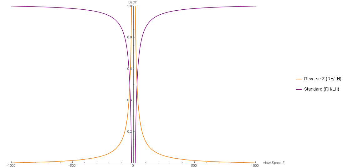
It’s also possible to completely remove the need for a fictional far plane and reduce potential rounding and truncation errors during projection and matrix concatenations to almost zero. To achieve this, we can simply assume that the far plane is infinitely far away, yielding:
Setting the near plane distance to
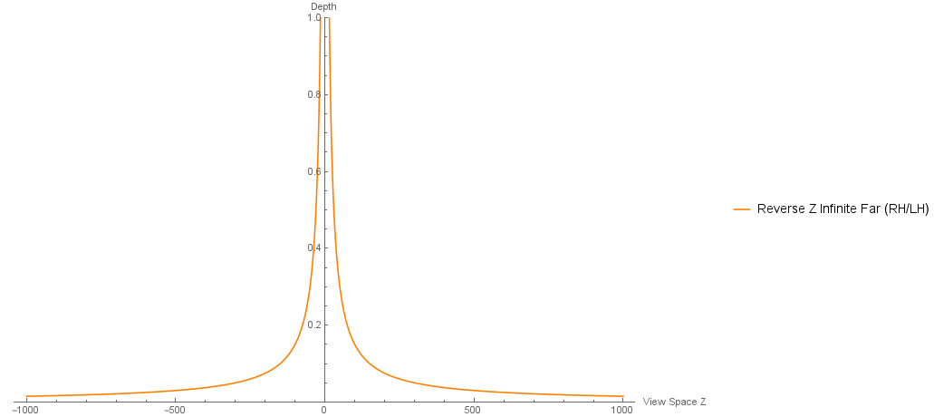
Note how the function is not starting to touch the x-axis when reaching the previous far plane distance.
An infinite far plane might not be the perfect fit for everyone. It has to be correctly handled throughout the whole codebase, requiring a bit of extra care and potentially a few hacks in certain scenarios.
Beyond Projection Matrices
Swapping the projection matrix is actually the easy part and there is still a little bit of work left to do (depending on the codebase you are working with). You have to…
- Switch to a floating point depth buffer (if you are currently using normalized integer formats)
- Clear depth to zero (instead of one)
- Adjust your depth tests from defaulting to less (or equal) to greater (or equal)
- Adjust all calculations which rely on the assumption that a normalized post-projection depth of zero lies in front of the viewer
- Keep the infinite far plane in mind for all your calculations – if you went down that path. Frustum corners for example are often calculated by transforming the screen space coordinates back to view or world space. Obviously, you will have to swap the depth values for the near and far plane, but you will also have to make sure that you won’t end up with infinite values for your far plane corners. Slightly biasing the screen space depth (something like
0+ϵ ) for the far plane can do the trick here - Keep in mind that OpenGL uses a NDC depth range in
[−1,1] , which requires some extra care. Using the OpenGL function glClipControl is one candidate for the job
Inversing Reverse Z
Multiplying with the inverse of the current projection matrix is a common approach to move the normalized post-projection coordinates back to view space.
But: in a lot of scenarios it is already sufficient to apply this transformation to the
Using this approach it is possible to derive the depth linearization functions fitting to each of the projection matrices depicted above:
Standard projection matrix (RH):
Reverse Depth projection matrix (RH):
Reverse Depth projection matrix with an infinite far plane (RH):
The left-handed counterparts are simply the negation of the right-handed functions.
As a small side note, when using those functions in shaders: make sure to prepare as much as possible on CPU side and to pass the prepared constants as uniform or constant buffer values. Taking the Reverse Depth linearization function as an example:
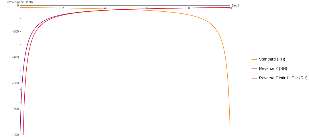
… and that’s all there is to it. To sum it up, the following plot shows the linearization functions with the near plane distance set to
Further Reading
- Reverse Z
- Projection Matrices